Monday, August 18, 2014

Makeblock -- YAAR!!

No, Makeblock is not a pirate microcontroller -- it's yet another Arduino robot.
Makeblock Gold starter kit

The August 13 Tech In Asia article "This Chinese startup lets kids easily make and program their own robots" is sort of an update of one of the Arduino robot companies that's been around for a while. They're a Shenzhen company that did a very successful Kickstarter, ending up with over six times their original $30,000 funding goal. According to the Tech In Asia article:
"...Makeblock, a startup from Shenzhen, offers a cheaper, more practical approach. The company sells robotics kits for as little as US$120 and enterprise kits for up to US$500. Makeblock makes 200 different mechanical parts and growing, which can be programmed using either Arduino or Scratch – the latter is an MIT-developed drag-and-drop programming environment for kids to learn the fundamentals of coding. CEO Jasen Wang says kids can easily make their own toy robots, while more serious hobbyists and even professionals can create robots to be used for more practical applications. Once a robot is built, it can be controlled via mobile app..."
A Wired article from 2012 titled "Robotics Hacker Erects Open Source ‘Lego for Adults’" gives some of the backstory about Makeblock:
"Jasen Wang once bought a home robotics kit. He had studied aircraft design in college and spent years at an electrics engineering outfit, but he still found the instructions completely incomprehensible. And the pieces were flimsy. And after he broke two of them, he gave up entirely. The good news is that he resolved to create his own robotics kit that was actually worthy of the name. The result is Makeblock, a set of flexible components — including slots, wheels, timing belts, and motors — for building robotics...You can even integrate these components with Lego blocks, as well as open source Arduino circuit boards and various other motors and standard industrial parts. And all of Makeblock’s schematics are open source, meaning anyone can build compatible parts or try to improve upon the designs...the company has built a custom-designed servo because Wangs says the ones already on the market weren’t adequate for robotics. And he’s not entirely happy with the existing integration system, so the company is building a new electronic platform that uses modular, color-coded connectors to make it easier to attach circuit boards and sensors...The key to Makeblock’s combination of sturdiness and flexibility are the threaded slots made from aluminum. Wang hit upon the idea at his day job. Although he knew he wanted to build a better robotics kit, he had no idea how. One day, he was asked to learn more more about the production side of the business, so he was sent to the factory to be trained in assembly work. It was here that he came across an aluminum part with a threaded slot, enabling engineers to add screws or connectors anywhere on each piece."
A more recent 2013 article from Make magazine gives Makeblock kudos for the high quality
High quality aluminum parts
parts.
"Compared to t-slot aluminum beams, Makeblock is much more sophisticated. It has threaded grooves running along the length of the beams, bolt holes running parallel to the grooves, as well as threaded holes on the ends of the beams. You can really get a sense of these features in the photo to the right. While the beams are great, Makeblock has created an impressive array of additional parts. The wheels and treads are extremely robust. There’s a nice variety of connector plates."
The electronics kit for Arduino and Scratch is $99 and looks like a pretty good package (it's just the electronics).
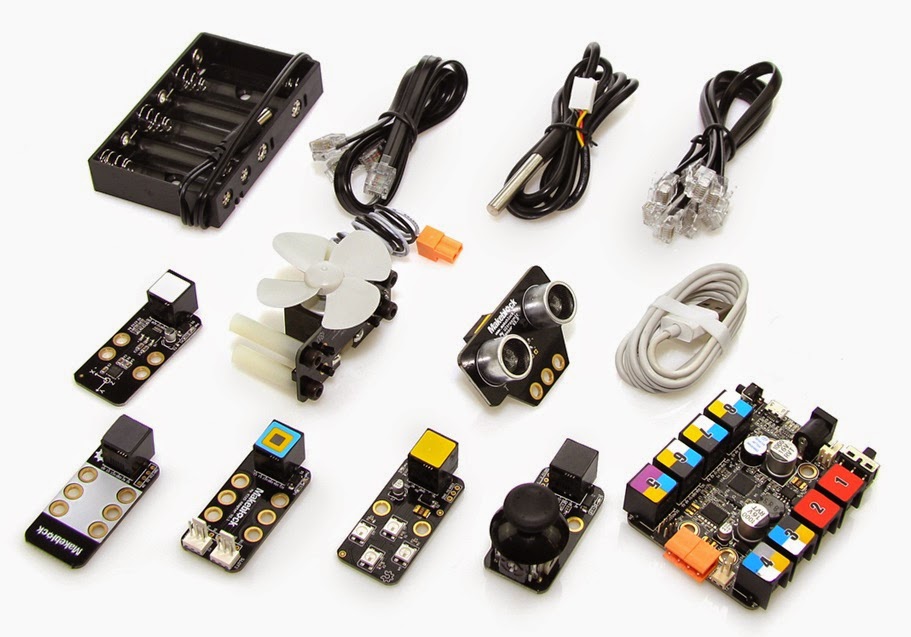
Electronics kit for Scratch and Arduino

It looks like Makeblock would be an excellent starting point for a person who wants to just build a robust robot and doesn't feel the need to cut and shape every part by hand. I don't think you have to worry about your Makeblock robot falling apart because you didn't cut components to just the right dimensions or weren't an expert with a CNC router or a laser cutter.

Maybe I'll ask for a Makeblock kit for Christmas!

**********

Sunday, August 17, 2014

Make Your Arduino Go Fast: A Modern Go-kart

Electric Arduino Go-kart (from Instructables)
As the Hackaday post "Electric Go-Cart Has Arduino Brains" says, most modern vehicles have lots of their functions controlled by computers (or microcontrollers / MCUs). The 2014 go-kart that's the subject of this post is truly a modern vehicle in that respect.

And...the go-kart will make your Arduino go pretty fast. In MPH, not GHz.

I first saw this go-kart mentioned on Google News in the Unocero article "Un Go-Cart eléctrico que usa Arduino," so if your native language is Spanish, you may want to read that version of this tech story. Google News is nice that way, because sometimes I see a non-English article that lets me know about a story I'd not have read if it wasn't in English. Google Translate certainly is not perfect or even almost perfect, but it usually gives a usable version of the article, and you can do more Googling based on the Skynet-translated version of a non-native language article.
Steering wheel showing LCD screen (from Instructables)

It appears the source of the story about this Kartduino is the "Electric Arduino Go-kart" Instructable done by a 15-year old from California. The Instructables write-up presents some of the technology used to build the go-kart, but it cautions the reader that it's not a complete guide to building the vehicle. Here's a taste of the write-up:
"The drive setup uses a Hobbywing Xerun 150A brushless electronic speed controller to control a Savox BSM5065 450Kv motor. Batteries are 3x zippy lithium polymer - 5 cells, 5000mah. The motor has two large fans I pulled out of an old computer for cooling, mounted right over the motor. The chain drive is a 1:10 overall ratio, using a 15 tooth on the motor chained to a 30 tooth on the jackshaft, and a 9 tooth from the jackshaft to a 45 tooth on the wheel. The tires are 10" diameter so at 20 volts the top speed is around 30 mph. The ESC is controlled via PWM from the arduino. A throttle potentiometer on the steering wheel controls this. Constant current is around 40-50A, and the batteries last around 30 minutes with an average speed of 10-15mph. It requires a small push to get started (really, the motor just has to be rotating) and accelerates extremely fast...This uses a sensorless brushless motor. They are not capable of starting under load. It may need a quick push before it can start. Don't try to start them under load. I already had one motor burn out because it stalled and the current burnt the coils' insulation. Sensored motors overcome this problem."
I'm sure if the Humboldt Microcontrollers Group ever wanted to build a similar 'kartduino,' Ed and others in the group would have plenty of ideas and knowledge on how to improve the design, with 'sensored' motors or an alternate solution to the sensorless brushless motors that burned out on the design shown in the Instructables.
Go-kart's wooden electronics control box (from Instructables)

With regards to the MCU in this zippy little go-kart, the Hackaday post covers the different parts of the vehicle integrated with the Arduino.
"In addition to the throttle control, the Arduino is also responsible for other operational aspects of the vehicle. There are a bunch of LED lights that serve as headlights, tail lights, turn signals, brake lights and even one for a backup light. You may be wondering why an Arduino should be used to control something as simple as brake or headlights. [InverseCube] has programmed in some logic in the code that keeps the break lights on if the ESC brake function is enabled, if the throttle is below neutral or if the ESC enable switch is off. The headlights have 3 brightnesses, all controlled via PWM signal provided by the microcontroller. There is also an LCD display mounted to the center of the steering wheel. This too is controlled by the Arduino and displays the throttle value, status of the lights and the voltage of the battery."
An interesting alternative kartduino I ran across whilst doing research for this post is the
LOLrioKart (by MIT student)
LOLrioKart (see picture at left). This slightly-strange vehicle was created from a shopping cart by a Massachusetts Institute of Technology student. Might be handy for going on a quick trip to Wildberries or the Co-op for groceries.

Speaking of modern vehicles and the increasingly important roles played by MCUs in vehicles, maybe Ford, another vehicle manufacturer, a microcontroller manufacturer or an electronics distributor will in the future want to sponsor a Humboldt Microcontrollers Group project to design and build a modified version of Steve Salzman's vehicle, with upgrades that allow it to parallel park itself as well as generate and track all sorts of vehicle operation data. That will be a fun project!

**********

Saturday, August 16, 2014

Using Arduino For Mind Control

This isn't a post about using a microcontroller (MCU) to control someone's mind -- it's a post about how to use an Arduino device that lets you use your brainwaves to manipulate inanimate objects.
OpenBCI prototype called "Frankenboard"

Here's how the August 11 article "Building Mind-Controlled Gadgets Just Got Easier" from IEEE.org explains this new brain-computer interface (BCI).
"Their system enables DIYers to use brain waves to control anything they can hack—a video game, a robot, you name it. “It feels like there’s going to be a surge,” says Russomanno. “The floodgates are about to open.” And since their technology is open source, the creators hope hackers will also help improve the BCI itself. Their OpenBCI system makes sense of an electroencephalograph (EEG), signal, a general measure of electrical activity in the brain captured via electrodes on the scalp. The fundamental hardware component is a relatively new chip from Texas Instruments, which takes in analog data from up to eight electrodes and converts it to a digital signal. Russomanno and Murphy used the chip and an Arduino board to create OpenBCI, which essentially amplifies the brain signal and sends it via Bluetooth to a computer for processing."
Current OpenBCI board
One nice aspect of Arduino is that it's getting more and more people who aren't electronics experts, computer programmers or engineers involved with physical computing. The IEEE article says they are "artists who met at Parsons the New School for Design." In the Humboldt Microcontrollers Group, there is a forester, a biologist, and an artist. And we'd love to have more non-engineers and others whose main experience and training is not in the field of electronics. The Arduino movement seems to encourage a whole new spectrum of people to see how they can apply MCUs and other modern electronics to their particular field of interest.

I haven't quite figured out if I think OpenBCI will be around for the foreseeable future. They seem relatively legitimate, but their website appears to be either very new or not a high priority for the founders of OpenBCI. Quite a few of the webpages on the site say 'Under Construction.' Even the 'Getting Started' page says it's under construction. But IEEE is a pretty reputable organization, and I don't think they'd have published the article if they weren't comfortable that the project was legitimate. Overall, though, it appears you'll get the OpenBCI hardware if you want to spend the $399 on either the 8-bit or 32-bit board kits. They also have a GitHub site that contains "the core OpenBCI hardware and software frameworks."

In addition to the IEEE August 2014 article about OpenBCI, there were a number of articles in early 2014 when OpenBCI did a successful Kickstarter campaign, getting more than twice their original goal of $100,000. Wired did an article in January 2014 titled, "These Guys Are Creating a Brain Scanner You Can Print Out at Home." The article featured a 3D printed 'brain scanner' headset that they called the Spider Claw 3000. Here's the article's description of the brain scanner:
"Spider Claw 3000" 3D printed 'brain scanner'
"It includes sensors and a mini-computer that plugs into sensors on a black skull-grabbing piece of plastic called the “Spider Claw 3000,” which you print out on a 3-D printer. Put it all together, and it operates as a low-cost electroencephalography (EEG) brainwave scanner that connects to your PC...You can target up to 64 locations on the scalp with a maximum of 16 electrodes at a time."
The $399 starting price for the OpenBCI is too steep for my budget, but I'm sure there will be some pretty interesting developments with this equipment in the next few years. The IEEE article mentions three projects:
"Audette, the engineer from Creare, is already hacking robotic “battle spiders” that are typically steered by remote control. Audette used an OpenBCI prototype to identify three distinct brain-wave patterns that he can reproduce at will, and he sent those signals to a battle spider to command it to turn left or right or to walk straight ahead. “The first time you get something to move with your brain, the satisfaction is pretty amazing,” Audette says...In Los Angeles, a group is using another prototype to give a paralyzed graffiti artist the ability to practice his craft
Chip Audette and brain-controlled Hex Bug battle spider (from IEEE)
again. The artist, Tempt One, was diagnosed with Lou Gehrig’s disease in 2003 and gradually progressed to the nightmarish “locked in” state. By 2010 he couldn’t move or speak and lay inert in a hospital bed—but with unimpaired consciousness, intellect, and creativity trapped inside his skull...They’re using OpenBCI to record the artist’s brain waves and are devising ways to use those brain waves to control the computer cursor so Tempt can sketch his designs on the screen...David Putrino, director of telemedicine and virtual rehabilitation at the Burke Rehabilitation Center, in White Plains, N.Y., says he’s comparing the open-source system to the $60,000 clinic-grade EEG devices he typically works with...Putrino hopes to use OpenBCI to build a low-cost EEG system that patients can take home from the hospital, and he imagines a host of applications. Stroke patients, for example, could use it to determine when their brains are most receptive to physical therapy, and Parkinson’s patients could use it to find the optimal time to take their medications
."
I wonder what some imaginative teenagers who have a lot of time and energy on their hands will come up when they start hacking OpenBCI...

**********

Friday, August 15, 2014

NASA Spaceship And Mission Control Desk

Spaceship in bedroom
You have to watch this video of a homemade NASA spaceship and Mission Control desk, part of which is controlled by an Arduino.

The above video is featured in the June 26 "Making Fun: Kid’s Room Spacecraft" post on the Make magazine website. The Mission Control desk featured in the above video and Make post was highlighted in a February 19 Make post, "Making Fun: Mission Control Desk," and was explained in this video. If you liked the video and are interested in details of how Jeff built some of the parts, make sure to read the two posts linked above.

After watching that spaceship video, I was both inspired and embarrassed. Inspired by the awesome job Jeff Highsmith did of building the Mission Control desk for his sons, then later building a NASA spaceship that's linked to the Mission Control desk.
Control panel in spaceship

As someone interested in learning about microcontrollers (MCUs) and about building things with MCUs, I was very much inspired by the variety of switches, lights, controls and realistic panels on the amazing desk and spaceship that Jeff built for his sons. As an engineer I was also inspired when he said in the video, "I put in an iPhone dock for future expansion. For now it will just play video from NASA, but in the future I plan to have some homemade satellites to monitor." I don't know if he meant homemade satellites that hang from the ceiling of his son's room, or if he is figuring that in a few years, there will be civilian satellites and he plans to have one or several of those civilian satellites be his. Either way I'm sure his expanded system will be cool, and his sons will have a great time with
Mission Control desk
the desk, the spaceship, the satellites and other additions Jeff and the boys make to their private space program. Can you imagine how much those two boys are going to know about electronics and building stuff by the time they reach high school!

Now to the embarrassing aspect of the Highsmith Space Program. I'm a bit embarrassed I never made anything half as cool as that for my kids. I'm also a bit embarrassed that the Humboldt Microcontrollers Group hasn't come up with a really unique and interesting project that four or more people want to put a bunch of knowledge and skill into that will make people who see it say, "Whoa, that's really awesome!"

There are a couple things that I want to do a little differently as a result of watching Jeff Highsmith's videos and reading his Make magazine posts about the Mission Control desk and the spaceship.
Payload bay remote camera monitor

The first thing to do differently with MCU projects is to 'think big while paying attention to details.' Jeff appears to have had a 'big picture' idea of what he wanted for his sons -- starting with a homework desk that can convert into a NASA Mission Control desk, then extending the space theme to his other son's bedroom with a spaceship. But what makes the desk and spaceship fantastic accomplishments is the close attention to the details. The control panels have complex and extremely realistic looking labels, switches, lights and controls. To make the experience authentic for his kids, Jeff incorporated recordings from NASA and simulations of actual astronaut problems. I realize the only way to tackle a large project is to break it down into small steps, but you have to have a good picture of what the large project will look like, and you have to pay attention to the small steps. When you know the big picture, and you're taking care of details, then commitment and perseverance have to kick in.

Mission status light panel
So, for the Humboldt Laser Harp and the Electronic Light Orchestra, the Humboldt Microcontrollers Group should discuss, agree on and document what the big picture is. How much time and effort do people want to put into that project. Next we should get more specific, more detailed on the finer points of what we'd like the Humboldt Laser Harp to look like and to do from both a music and a lighting standpoint.

The second thing to do differently on MCU projects is taking more photos and videos at each stage of a project, planning ahead of time the shots to capture for each project. Jeff's videos have excellent documentation of building the desk and spaceship. I became less embarrassed but no less inspired when I read that Jeff is a full-time videographer. That explains thinking things out enough ahead of time that he captured cool construction sequences while he was building the projects. It would be really good if the Humboldt MCU group could find a videographer or two who are interested in MCUs and electronics and would like to participate in the group's activities. They would know how to capture the story of a project, and they'd be able to put together a cohesive and impressive video.
Ardunio used to control instrument panel

I think I'll keep a link to Jeff's spaceship video handy and watch that regularly to keep me inspired and to remind me of how rewarding completion of a big, complex project can be.

**********

Thursday, August 14, 2014

Make Your Android Phone A Programmable Robot

If you've got a recent Android phone with modern sensors, a current Kickstarter project aims to turn that phone into a programmable robot.
Hippo-ADK basic board

The Hippo-ADK (Android Development Kit?) is profiled on Tech In Asia in the article, "This startup turns your Android phone into a fully programmable robot." While previous coverage of the Hippo-ADK, such as this Hack A Day post, focused mainly on the self-balancing capability of a two-wheeled robot made with Hippo-ADK and a gyroscope-equipped Android phone, the Tech In Asia article makes it clear the concept is to make good use of whatever sensors are in the phone.
"The mass adoption of Arduino opened up hardware prototyping to the world, serving as a common platform and large community for millions of hobbyists and professionals. But even though an Arduino board only costs about US$25, finding and purchasing many of the other components can be time consuming and expensive. That’s why Shenzhen-based Hippo Devices is developing a new, easier to use controller board called Hippo-ADK. The device plugs into a user’s Android phone, allowing it to utilize the phone’s proximity sensor, gyroscope, Bluetooth, camera, and other features. “Everyone has a mobile phone, why not make use of it? Why not make use of these $300 worth of sensors that everyone already has?” says Hippo’s
Hippo-LEGO shield
marketing coordinator...Besides saving money on sensors, Hippo-ADK doesn’t require learning a new programming language like Arduino. Hippo offers a graphical drag-and-drop programming environment...the Java API...If you’re an Arduino junkie and you prefer to stick to your guns but would still like an easy way to take advantage of your phone hardware, it’s compatible with Arduino hardware and software...It comes equipped with several extra sensors baked into the board, including infrared, which can control home appliances like air conditioners and thermostats
..."
Hippo-Arduino shield
As mentioned in the article above, you can put your Arduino knowledge to good use with the Hippo-ADK, but you might also feel compelled to expand into some App Inventor or Java programming if you pick up some of the Hippo hardware. Arduino seems almost to be used by Hippo as a marketing tool, saying that they are "combining an Arduino-like microcontroller board with Android." Their board uses an STMicroelectronics microcontroller, not an Atmel MCU. The Arduino hardware Hippo is providing at this point is the Hippo-Arduino, a shield that connects Hippo-ADK and Arduino (see picture at right).
Instructables Hippo

The Kickstarter original funding goal of $10,000 has been met, but this isn't one of the viral crowdfunding projects at this point. With 14 days left, the total raised as of the evening of August 14 is $16,457. One aspect that may have caused some people to hold off on supporting the campaign is that building a self-balancing two-wheeled robot will cost significantly more than the $39 (early bird) or $49 for the Hippo-ADK. It looks like it would end up being a couple hundred dollars for all the parts for a self-balancing robot, assuming you're starting with an Android phone that has a gyroscope you can use for robot balance control. If you're interested in building that self-balancing robot, Hippo posted an Instructables for that.

Here's a bit of what the Kickstarter page says about the Hippo-ADK:
"Hippo-ADK connects with your Android devices in real time through USB and Bluetooth.This allows you instant access to sensors,switches, accelerometers, gyroscopes, magnetometers, communication modules (Wi-Fi, GPS, GSM), cameras, and LCD screens without even having to spend a dollar on optional parts. It is all on your Android devices...If you want to expand the capabilities of our firmware you can use Arduino language and IDE to program Hippo-ADK...For beginners, use the graphical programming platform App Inventor to create your first “Hello World” Hippo-ADK project in less than 10 minutes. For the more experienced, enjoy the variety of high-level customization available by our Java API...For those who want to make even cooler stuff with Hippo-ADK such as robots and intelligent homes, we provide expansion boards and modules to facilitate more rapid development."
I like the concept of using the power and features of a smartphone to help power a robot. And the Hippo is certainly not the first -- there are other robots powered or enhanced with smartphones, including Romo and SmartBot. The Wall Street Journal (WSJ) even had a January 2014 article titled "Smartphone Robots Could Be About to Invade Our Homes." The real question is what the killer app will be for phone-carrying robots. Part of the challenge for mass production is the huge array of phone sensors, features, processors and operating system versions on the billions of cell phones being used around the world. Connecting your phone to your robot will be commonplace when it has clear benefits, as opposed to doing it because you can. As the head of iRobot Corp. said in the WSJ article,
Hippo non-balancing robot
"...the challenge is to meaningfully integrate a mobile device and a robot. "Are you connected because of a fad or because the customer experience is greatly enhanced by the addition of this technology?"
I'm looking forward to the first phone-bot that figures out the answer to this question. Not only will our robots be able to do more and be more interesting, I'm betting our phones will see new innovations, sensors and capabilities if they're frequently used to enhance our personal robots.

**********

Wednesday, August 13, 2014

Unboxing (And Updating) A Texas Instruments MSP430FR5969 Ultra Low Power FRAM MCU

[Tonight's post is by Ed Smith, a member of the Humboldt Microcontrollers Group]

I just received a Texas Instruments (TI) MSP430FR5969 LaunchPad! This is my unboxing post, I'll also cover updating the onboard programmer's firmware for use with Energia.

We'll kick things off with a few specs, or at least a quick product description. This is an unboxing not a review, after all.

The MSP430FR5969 MCU is aimed at extreme low power consumption, to the point where when it is operating at full power it consumes ~100µA/MHz. That's quite low; at 16MHz it's consuming a measly 1.6mA. In the various sleep modes the power draw is measured in handfuls of micro-amps, and in deep-sleep it even gets down to nano-amps.

The FR5969 LaunchPad takes that MCU and gives it a home, as well as a built in programming interface, breakout headers (with very nice labels, as we'll see later), buttons, LEDs, lots of jumpers, and a 0.1F supercap. That's not µF, that's not mF, that's a tenth of a Farad, something that would have cost a tremendous amount of money a decade ago.

For bonus points, Energia already supports this platform.

The box is a simple affair, nothing especially flashy other than the rocket logos. Even those aren't flashy per se, not compared to modern marketing anyway. It's a sturdy box, I approve.


Inside the box we find, not surprisingly, an anti-static bag with a LaunchPad in it! There actually is a surprise in here, I'll focus on it later.

This is the bottom of the board, in case you hadn't guessed.
Here we have the top side, there are hints of greatness here too.
The last thing in the box is a beefy mini-USB cable, to connect the LaunchPad to your computer for programming and/or power. It's very nice of TI to include this, and I appreciate it.


Out of the bag we get more detail, we can see the two user buttons plus reset button, a wide array of jumpers for controlling how much of the MCU core is connected to the debug/USB/power side of the board, as well as the supercap and two user addressable LEDs. Note the amount of text near the headers!
On the bottom there are two things I really, really like. One is the amount of pin information printed near the headers, I'll zoom in on it in a bit. The other is the plastic standoffs. This is something lacking in the vast majority of dev boards out there.
The board sits nicely on the standoffs and bottom headers, no worries about short circuits to metal tables no MCU tipping over when you try to plug something in. It's a small thing, but I appreciate it.
The silkscreen on both sides of the board is very informative, it gives you plenty of options for charging or not charging the supercap, using or not using the supercap, current monitoring, voltage monitoring, USB power or external power, etc. It also has significantly more pin information next to the headers than one usually sees. Not only the port numbers, which is standard, but also designations as to which pins do what. Serial TX and RX are marked on most boards, MOSI/MISO/SCK(SCLK) for SPI and SCL+/SDA+ for i2c are not usually marked, and they are here. This cuts down on the amount of time needed looking at datasheets and pinout diagrams substantially. I dearly hope that other companies will follow TI's lead here; they seem to be thinking about the end user.

All is not roses with the FR5969 LaunchPad however. Maybe it is roses, and we're getting to the thorns now. In any event, there are two revisions of this MCU. The first revision to come out, and the new Energy Trace revision. Energy Trace adds a solid set of features to check where the energy is going, but it also requires a newer firmware version for the on board programmer. Unfortunately for some reason or another it doesn't seem to have made it on to the first round of Energy Trace boards! On the plus side, updating the firmware is fairly easy.

Updating the MSP430FR5969 EZ-FET Firmware via Energia

This guide assumes you're going to be using Energia to do your programming, or at least your firmware updating. Code Composer Studio also ships with an updater I believe, and you can download a standalone command line updater as well.

The first step is to open Energia and find the Update programmer menu. It's under the Tools menu and is not hard to find.

You will need to run this a few times, as there is a bug in the update script somewhere that times out after updating one device, and there are three devices on this board that need updating.

For the moment, run it until you start getting errors. I was able to update two out of three devices without any further effort.

Once you start getting errors you will need to close Energia and download the TI MSP430 Flasher utility, the command line program I mentioned above, you can find it here:
 MSP430 Flasher Link


Once you have downloaded and installed it, you need to open two folders. One is the MSP430Flasher install directory (click the pictures to the right for a larger size), the other is the mspdebug directory inside the Energia install directory. The pictures to the right show the paths on my computer.


Once you find the two directories you want to copy HIL.dll and MSP430.dll from MSP430Flasher into Energia's mspdebug directory. Backing up Energia's copies of those two files isn't a bad idea, I created a directory called "OEM" and moved the originals into it, then copied the new HIL and MSP430 dlls.


Once you have copied those two files, re-open Energia (if you didn't close it before, close it and re-open it) and run Update Programmer again. Instead of throwing errors it should happily update the remaining piece of firmware. If you feel like being sure, run it again and make sure it's happy that time too.

Presto! Your MSP430FR5969 LaunchPad is now ready to use, enjoy!

- Ed Smith

**********

Tuesday, August 12, 2014

Linduino: USB-Isolated Arduino, Working With DACs and ADCs

Linear Technology products, including ADC & DAC
So a lot of microcontroller (MCU) topics I write about in this blog are mini-research projects for me, because I'm new to MCUs and to electronics in general. Through my research I get to learn more about MCUs and how they're used, and, with a little luck, you get to be informed or amused, or both, by the posts here. But today's topic, Linduino, DACs and ADCs, is even further than normal from my experience and knowledge base, so this post will just give you an overview of the Linduino board from Linear Technology.

"Linduino is a USB-isolated Arduino," an August 11 post on EDN.com, caught my interest because of the *duino name and because the post mentioned applications involving temperature sensors (Humboldt MCU Garden project), audio systems (Humboldt Laser Harp and other music-light instruments) and car systems (Ed Smith is a great resource for vehicle-related MCU projects, possibly something with on-board diagnostics, or OBD). Familiarity with the Linduino board isn't required to do any of the aforementioned Humboldt MCU projects, but at some future point a Linduino could provide major benefits for us. If nothing else, it would be worthwhile to connect with some of the *duino people at Linear Technology, the manufacturer of the Linduino, to expand and strengthen the statewide and worldwide network of the Humboldt MCU community. Plus, their headquarters are in Milpitas, California, so maybe they'll get the urge to drive north behind the redwood curtain and participate in a Humboldt Microcontrollers Group meeting or a Humboldt Makers meeting!
Linduino board

Onward to tech specifics about Linduino. The EDN blog post mentioned above says:
"My pals over at Linear Technology have developed the Linduino board to drive their ADCs (analog to digital converters) and DACs (digital to analog converters) as well as temp sensors and other devices...in addition to the normal shield headers on an Arduino, there is a header that Linear Tech has used for years to drive their demo boards. This computer interface function used to be done with their DC590 interface board. Indeed, the firmware that comes shipped with the Linduino emulates that board, so you can run the original Linear Tech interface program on your PC...The Linduino board will accept all the shield mezzanine boards for Arduino, but has this extra header to control Linear Tech demo boards...Linear Tech also used one of their USB isolators on the Linduino board. This means that the board and what you plug into it are galvanically isolated from the computer you have the USB plugged into. This means you can measure things off a car or an audio system without worrying about ground loops polluting the measurement...Since Linear Tech is also a power supply chip company, they beefed up the power supply on the board, using a switching regulator to replace the linear regulator on the Arduino. This means you can get 750mA out of the power system. Since a USB can’t supply this much power, that means you have to feed the board with an external wall wart. Now you have the power to drive actuators or other heavy loads..."
We're in the early stages of refining the Humboldt Laser Harp, and depending how deep we get into developing the Humboldt family of laser harps and other light-music MCU instruments, there may come a time when we'll need, or at least want, a board that can be used on "an audio system without worrying about ground loops polluting the measurement." That's one of the reasons I am interested in the Linduino board.

The main Linduino webpage has lots of info and links about the board, including several internal blog posts and an overview video about Linduino. Since getting two viewpoints about what the board is and does might help you better understand its value, here's the Linear Technology webpage description of what Linduino is:
DC2026A-KIT
"Linduino is Linear Technology’s Arduino compatible system for developing and distributing firmware libraries and example code for Linear Technology’s integrated circuits. The code is designed to be highly portable to other microcontroller platforms, and is written in C using as few processor specific functions as possible. The code libraries can be downloaded by clicking the Downloads tab above and used as-is in your project or individual code snippets may be viewed in the Code section of a supported part. The Linduino One board (Demonstration Circuit DC2026A) allows you to test out the code directly, using the standard demo board for the particular IC. The Linduino One board is compatible with the Arduino Uno, using the Atmel ATMEGA328 processor. This board features a 14-pin “QuikEval” connector that can be plugged into nearly 100 daughter boards for various Linear Technology parts, including Analog to Digital converters, Digital to Analog Converters, high-voltage power monitors, temperature measurement devices, RF synthesizers, battery stack monitors, and more."
Humboldt Laser Harp and Ed Smith
Linduino is not inexpensive, so participants of the Humboldt Microcontrollers Group won't be buying them on a whim like a $3 Arduino Micro clone from China. But if someone has a genuine need for the board, especially a business-related, revenue-generating need, it would be good to know it's available. You can order the board from this Linear Technology page, and there are two options. One option is the DC2026A-KIT for $125, and the other is just the DC2026A board for $75. Digi-Key, Newark and Arrow are also distributors for Linear Technology.

So now you have a general idea of what the Linduino board is and can do, and you've got links above that lead to more info about this member of the continually-expanding *duino family. I'll have to check in with Ed Smith to find out exactly what value this tool might have for us while working on the Humboldt Laser Harp, the Humboldt MCU Garden or any other MCU projects our MCU group or maker group gets involved with.

**********